With recent developments in technologies like MIMO, femtocell and LTE, the RF device testing is reaching new dimensions. Read on to find out what’s new in this field.
Millions of devices these days operate and communicate in radio frequency (RF) range, which spans from 3kHz to 300GHz of the electromagnetic spectrum. From radio frequency identification (RFID) tags attached to clothes in shopping malls to Bluetooth headsets, and from Wi-Fi-enabled laptops to complex medical devices, this technology has become inevitable in our lives. This steep increase in the number of devices has led to the introduction of several industry standards. In order to bring out a new RF instrument to the market, the designer has to take it through a series of tests and ensure that the device meets the industry standards.
The testing and verification process for RF applications is done at two stages - component level and system level. In component level testing and verification, each design component or building block of the system (amplifier, multiplexer, filter, modulator/ demodulator, phase-locked loop, and transmitter and receiver antennae) is considered as a subsystem and its parameters (modulation scheme, frequency, sensitivity, saturation, etc) are tested independently. In system level verification, the tests and measurements are done on the RF device as a whole, and it simulates what exactly that system is going to perform.
With a wide range of applications and systems incorporating the RF principle and the extensive researches happening in this field, it is important for a design engineer to stay updated with the latest technologies and trends in RF communication.

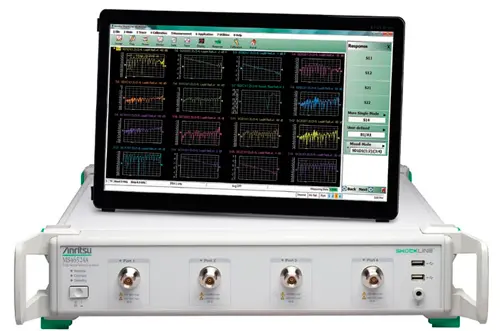
Fig. 1. Anritsu MS46524A with monitor
Technology trends
The generally growing demand for higher throughput, faster results, customisability, reduced cost and better connectivity has led to greater researches in the field of wireless communication. Though the test and measurement field for RF devices also adapts to these enhancements, this field has not witnessed many path-breaking innovations in the past few years.
Analyses in real time. The previous generation of test and measurement equipment for RF devices faces a few challenges. With the dynamic nature of modern-day RF signals, it is necessary to understand the amplitude, frequency and modulation parameters over short and long intervals of time.
One of the most popular products these days is the real-time spectrum analyser that has an operating speed that matches the speed of the system it is simulating. In real-time spectrum analyser (RTSA) architecture, fast and continuous sampling and calculations are performed in order to keep up with the changing input signals. This helps the user to view events that were invisible in previous architectures like swept tuned analyser and vector signal analyser. Latest RTSAs let you trigger these events, selectively capture them into memory and analyse them extensively in multiple domains. R&S FSVR series by Rohde & Schwarz, N9030A and N9040A series by Keysight Technologies, and SPECMON RSA3000 and RSA5000 series by Tektronix are some examples of RTSA.
Heat dissipation. Proper power dissipation techniques are essential for every electronic device. In case of instruments used for field applications, it is not practical to use bulky cooling systems as this increases the size and weight, and reduces the mobility of the testing instrument. Since such devices operate for long hours in rugged environmental conditions, these are placed inside a chassis that has an electrically-insulating and thermally-conducting layer of coating. This helps in the safe dissipation of large amounts of heat generated in an RF test and measurement instrument.
MIMO. Multiple-input and multiple-output (MIMO) is the method of using multiple antennae at both the transmitter and receiver sections in radio communication technology. It increases the link capacity, link reliability and spectral efficiency by exploiting multipath propagation, which was previously considered as interference. The fact that MIMO needs no extra bandwidth or transmit power in order to increase the data throughput and link range made most of the modern researches to be concentrated on this area.
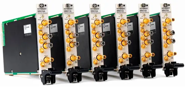
The physical layer performance characterisation can be performed by the MIMO PXI test solution from Keysight Technologies. This solution provides flexibility for a validation engineer to try out a variety of test cases and ensure that the WLAN design works perfectly. In case of MIMO beamforming, even a slight inaccuracy in phase relationship will lead to irrelevant and misleading results. MB5 MIMO beamforming testing system was introduced by Spirent to automate the phase calibration in order to meet the tight tolerance values required by MIMO beamforming.

Fig. 2. Keysight M937xA network analyser
Femtocell. Femtocell is a small, low-power wireless access point that is used to provide better coverage for cellular networks inside homes, office buildings and public spaces. It is one of the recent advancements in mobile communication; the device resembles a wireless router.
E6650A EXM wireless test set by Keysight Technologies and EAST Femtocell by EXFO Inc. are one-box test solutions dedicated to the manufacturing of femtocells. These solutions can easily measure various formats of femtocells like 2G, 3G, 4G and WLAN.

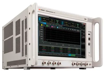
Fig. 3. Keysight uxm wireless test set E7515A
Long-term evolution (LTE). LTE and LTE Advanced are becoming global standards for mobile broadband data and high-definition audio. LTE based networks are also used as standards for providing public safety enhancements such as police, fire fighting and emergency medical services.
MD8430A signalling tester (base station simulator) and ME7873L LTE RF conformance test system by Anritsu and E6621A PXT wireless communications test set by Keysight are products exclusively for the LTE and LTE Advanced technologies.
Commercial LTEs can only transmit up to a maximum power of +23dBm. In order to provide extra coverage for critical systems in band 14, release 11 of 3GPP (3rd generation partnership project) has made the maximum transmit power for LTE devices in this band to be +31dBm. R&S CMW500 wideband radio communication tester, a joint effort by Rohde & Schwarz and Elektrobit, now meets this require ment, i.e., measuring a high output power of +31dBm.
Instruments you need |
Let us take a look at the basic test and measurement equipment required to evaluate an RF device. RF power meters. Spectrum analysers generally have the capability of measuring up to about 100mW of power. For measuring values above that, we generally use a power meter. Power meters measure the transmission power of an RF device over a wide frequency range and display high-accuracy results. But a power meter has a limited amplitude measurement range and gives no information on the frequency composition of the signal. RF signal/spectrum analyser. This device measures the magnitude of an input signal in a frequency domain using narrowband detection techniques. Though the accuracy level is low compared to power meters, the spectrum/signal analysers can measure values as low as -150dBm. Spectrum analyser checks if the transmitter is generating appropriate power spectrum and the vector signal analyser measures how much modulation distortion is created by the device. Network analyser. It measures the response of a device at radio frequencies and displays that in rectangular co-ordinates, polar co-ordinates or a Smith chart. It lets you determine parameters such as transmission losses and gains, return loss, impedance match, phase measurements and group delay over a wide range of frequencies for components like filters and amplifiers. By evaluating the characteristics, one can determine the behaviour of the component in the intended RF device. RF signal generators. These instruments are used to create a stimulus signal for testing components, devices or systems. It either generates the signals internally or uses the signal created externally and downloaded into the instrument. These are used for receiver sensitivity tests, bit error rate (BER) tests, adjacent channel rejection and two-tone intermodulation tests. |
Testing multiple devices. Minimising time consumption for testing is necessary for reducing the cost of production. Leading players in the industry have come up with instruments that can test multiple devices at a time.
The upgraded MT8870A universal wireless test set by Anritsu can simultaneously measure four wireless devices, through parallel processing of four different modules integrated in this test set.
R&S CMWS switch matrix, together with CMW500 wideband radio communication tester from Rohde&Schwarz, concentrates more on the reducing bit error rate (BER) measurements in the receiver section by introducing an advanced RF switch device. The RF switch matrix collects test signals from 24 RF ports, which can be connected to a maximum of 24 devices, and all these signals are processed simultaneously.
The new low-cost switching and instrumentation architecture |
In September 2014, the AdvancedTCA Extensions for Instrumentation and Test (AXIe) Consortium announced a new standard named AXIe-0, which is expected to broaden the use of AXIe, targeted for low-cost modular instrumentation and switching applications. It is an ideal platform for users who require major capabilities of AXIe-1 at an affordable price. AXIe-0 is completely upward compatible with the existing specification AXIe-1, thereby making it a subset of the mainstream standard. This means that the AXIe-0 module can be used in AXIe-1 chassis. Features like module size (3.05x27.94x32.26 cms), board area, slot scalability and horizontal and vertical configurations of AXIe-0 are the same as the AXIe-1 base architecture. The cost has been cut down by the use of LAN interface, single power supply voltage of -48V reducing zone 2 connectors from five to two, and elimination of zone three connectors and intelligent platform management interface (IPMI). AXIe-0 can be used for applications that require AXIe's space, power and form factor, but do not necessarily need a high-speed data infrastructure. Some of the application areas of the new specification include large switching systems and RF interface units for military and aerospace electronic functional test, VME eXtensions for Instrumentation (VXI) replacement in mil/aero, custom instrumentation and functionalities by system integrators or users, general purpose (loads, frequency counters, etc) and data acquisition. |
Vector signal transceiver. With increasing complexity of RF signals, engineers are often challenged to make a system with improved functionality without increasing the cost or time for the test. The introduction of field programmable gate arrays (FPGAs) makes this task simple by increasing programming flexibility. These FPGAs can be configured to implement custom hardware functionality through software-defined platforms.
Vector signal transceiver (VST) by National Instruments combines vector signal generator and vector signal analyser and provides real-time signal processing and control with a user-programmable FPGA. The users can customise the RF instrument to the pin so as to make it application specific.
Author: Anagha P.

