Get maximum accuracy from your 12-Digit Frequency Counter using this GPS lpps Timebase. It connects to the external timebase input of the counter and will let you achieve measurement accuracy close to that of an atomic clock. You can either build it into the frequency counter or use it as a separate module.
ARE YOU KEEN to build the new 12 -Digi t High -Resolution Frequency Counter described in the January and February 2014 issues of EPE1 It’s a world-first DIY design, but you will also want to get the very best accuracy to go with its 12-digit resolution.
To do this, you don’t need our complex GPS-based Frequency Reference (EPE, April-May 2009), although this can be used if you have it. If you don’t, then there’s a much simpler and cheaper approach: purchase a cheap GPS receiver with lpps output, bung it on a small interface PCB and you get close to atomic-clock precision.
In fact, we promised in our February 2013 issue to publish such a device - and here it is. Build it for your frequency counter and you should be able to achieve a measurement accuracy of around ±1 part in 1011.
Simple circuit
Fig. 1 shows the circuit details. It looks simple, but that’s because all the complex circuitry needed to receive the signals from the GPS satellites and derive the lftz (lpps) pulses is inside the GPS module.
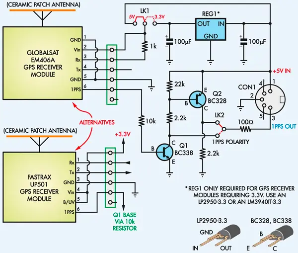
Fig. 1: the circuit consists of the GPS receiver module itself plus a couple of transistors (Ql and Q2) to buffer and level translate the 1Hz (lpps) pulses. Regulator REGl is required for GPS modules that operate from 3.3V DC.

Fig. 2: the pin connections for the GlobalSat EM-406A and Fastrax UP501 GPS modules. Check the pin connections if you use a different module.
We are specifying either of two GPS modules which are currently available from various suppliers: the GlobalSat EM-406A module, which is available from amazon.co.uk for around £40 or the Fastrax UP501 module from uk.rs-online.com. This is smaller and also priced at £40, but is becoming harder to buy. The project is also compatible with various other receiver modules, if you find the EM-406A or the UP501 out of stock.
Parts list |
1 PCB, available from the EPE PCB Service, code 04103131, 66mm x 46mm 1 GPS receiver module with in-built patch antenna and 1pps output 1 6-way SIL pin strip 1 3-way SIL pin strips 2 jumper shunts 4 M3 x 10mm untapped nylon spacers* 4 M3 x 25mm nylon screws* 8 M3 nuts Hook-up wire for GPS module 25 x 25mm doubled-sided adhesive foam (to secure GPS module) Semiconductors 1 BC338 Л/P/Vtransistor (Q1) 1 BC328 PVPtransistor (Q2) 1 LP2950-3.3 (TO-92) or LM3940IT-3.3 LDO regulator** Capacitors 1 100μF 16V RB electrolytic (or 2 if a 3.3V supply required) Resistors (0.25W, 1%) 1 22kΩ 1 1kΩ 1 100Ω 1 10kΩ 2 2.2kΩ *Only if project is built inside the frequency counter **Only for a GPS module which requires a 3.3V supply Extra parts for jiffy box version 1 UB-5 jiffy box, 83 x 54 x 31mm 1 5-pin DIV socket, PCB-mount 1 5-pin DIV socket, panel mount, for frequency counter 1 5-pin DIV plugs 1 2-core shielded cable 4 M3 x 10mm machine screws |
The type of GPS receiver module you’ll need is one that incorporates its own ceramic 'patch’ antenna for the UHF signals from the GPS satellites, while also providing an output for lpps (pulse per second) time pulses. It can operate from a DC supply of either 5.0V or 3.3V. A few currently available modules are listed in a panel elsewhere in this article.
The EM-406A has its own built-in GPS patch antenna and operates directly from 5 V DC. It features the SiRF Star III high-performance GPS chipset, very high sensitivity and an extremely fast time to first fix (ie, from a cold start).
The UP501 and other compatible GPS modules operate from 3.3V DC, so for these we have made provision for fitting a 5V-3.3V LDO (low dropout) regulator (REG1). You can use either an LP2950-3.3 regulator which comes in a TO-92 package or an LM3940IT-3.3 which comes in a TO-220 package.
Apart from the power supply arrangements, there is a simple buffer and level translator for the 1Hz pulses provided by the GPS module. This uses transistors Q1 (BC338) and Q2 (BC328) to ensure that the 1Hz pulses fed out to the counter have a peak-to-peak amplitude of 5V, regardless of the supply voltage used by the GPS module.
Link LK2 allows the 1Hz pulses to be inverted or not by the buffer, so that their ‘leading edges’ are positive-going regardless of their polarity out of the GPS module (some modules may output them as inverted.)
Why do we need to ensure that the leading edges of the 1Hz pulses fed EM-406A has its own built-in GPS patch antenna and operates directly from 5 V DC. It features the SiRF Star III high-performance GPS chipset, very high sensitivity and an extremely fast time to first fix (ie, from a cold start).
The UP501 and other compatible GPS modules operate from 3.3V DC, so for these we have made provision for fitting a 5V-3.3V LDO (low dropout) regulator (REG1). You can use either an LP2950-3.3 regulator which comes in a TO-92 package or an LM3940IT-3.3 which comes in a TO-220 package.
Apart from the power supply arrangements, there is a simple buffer and level translator for the 1Hz pulses provided by the GPS module. This uses transistors Q1 (BC338) and Q2 (BC328) to ensure that the 1Hz pulses fed out to the counter have a peak-to-peak amplitude of 5V, regardless of the supply voltage used by the GPS module.
Link LK2 allows the 1Hz pulses to be inverted or not by the buffer, so that their ‘leading edges’ are positive-going regardless of their polarity out of the GPS module (some modules may output them as inverted.)
Why do we need to ensure that the leading edges of the 1Hz pulses fed to the 12-Digit Frequency Counter are positive-going? Simply because it’s the leading edges of the pulses that are locked closely to the ‘atomic time’ provided by the GPS satellites. The counter uses the positive-going edges of the external timebase pulses to clock its main gate flipflop, so this ensures the highest measurement accuracy.
Assembly
All the parts fit on a PCB coded 04103131, measuring just 66mm x 46mm, which is available from the EPE PCB Service. Fig.3 shows the assembly details. Almost half of this tiny PCB is reserved for the GPS module itself, which is usually mounted using double-sided adhesive foam.

Fig. 3: follow these diagrams to build the GPS lpps Timebase Module. Omit CON1 if the unit is to go inside the frequency counter’s case and omit REG1 and its 100μF output capacitor if the GPS module uses a 5 V supply, eg the GlobalSat EM-406A. Alternatively, fit REG1 and the 100pF capacitor for the Fastrax UP501. Don’t forget to set link LK1 accordingly.
To allow for convenient connection back to the counter when it is being used remotely, we have provided space for a 5-pin mini-DIN socket (CON1) at the righthand end of the PCB. This allows you to use a cable fitted with a 5-pin DIN plug to link the GPS timebase back to the counter, at the same time providing the unit with +5V power.
Compatible GPS Modules |
The following GPS receiver modules should be compatible with this unit:
Note that for use in this project, the GPS receiver module should have a built-in ceramic patch antenna and also provide an output for the GPS- derived 1Hz pulses. Not all GPS modules currently available provide both these features. |
This socket is not needed if the PCB is fitted inside the 12-Digit Frequency Counter’s case. In this situation, the GPS PCB is linked to the counter’s main PCB using three short lengths of insulated hook-up wire.
Two other components shown in Fig.3 are required only if your GPS module needs a 3.3V DC supply, rather than 5 V. These are REG1 and the 100μF electrolytic capacitor connected between its output and ground. If you are using the EM-406A module (which requires 5 V) and you are also mounting the receiver inside the counter box, leave out CON1, REG1 and the 100μF capacitor. Conversely, install REG1 and the 100μF capacitor if you are using the UP501 GPS module.
As previously stated, LK2 must be fitted in the position that provides output pulses with positive-going leading edges (see scope grab - Fig.7).
Most GPS receiver modules, including those specified here, provide 1Hz pulses with this polarity anyway, so the jumper shunt will probably need to be in the upper position; ie, so that the pulses are taken from the non-inverting buffer output (collector of Q2).
Mounting
Fig.5 shows how the timebase PCB is mounted inside the counter box. This is the easiest mounting option and if you’re using the EM-406 GPS module (which is quite sensitive), it and others should be perfectly workable even if you are inside a building.
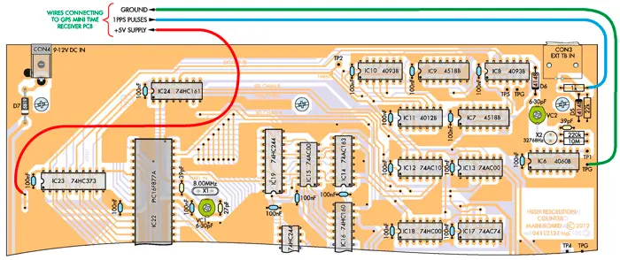
There are just three connections to be run to the main counter board: lpps signal, +5V and ground (GND). Fig.4 shows the wiring details. As you can see, the ground wire connects to the ground pin just to the right of IC6, while the +5V wire connects to a PCB via to the left of IC23. The wire carrying the 1Hz pulses from the GPS receiver connects to the righthand end of the lkQ resistor behind CON3.
Fig. 4: only three leads are required to connect the timebase module to the main PCB in the frequency counter. These leads are connected directly to the
GPS timebase board if it is mounted inside the counter case or run to a panel-mount DIN socket (installed on the counter’s rear panel) if the GPS timebase
is mounted in a separate case (see panel).
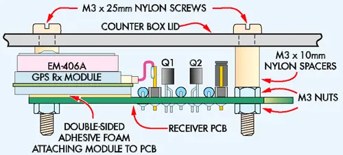
Fig. 5: the Timebase Module is attached to the lid of the case on M3 x 10mm untapped nylon spacers and secured using four M3 x 25mm nylon screws and eight M3 nuts (four used as spacers).
Building a standalone 1pps Timebase |
Some GPS receivers may not have sufficient sensitivity to work indoors. In that case, it will be necessary to install the timebase PCB in a small utility box which can then be positioned on a window sill (or wherever) for better satellite-reception. The unit can then be connected to the counter via a cable fitted with DIN plugs at either end. Fig.6 shows how the unit is mounted inside a UB-5 jiffy box. You will need to mount DIN socket CON1 on the PCB, then attach the PCB to the case lid using four M3 x 10mm machine screws and eight nuts (four used as spacers). A 15mm-diameter hole will then have to be drilled and reamed in one end of the box, in line with the DIN socket (ie, to allow plug entry). In addition, a matching 5-pin DIN socket should be mounted on the rear panel of the counter and its terminals run to the corresponding pads on the main counter PCB. Finally, you will have to make up a suitable cable with DIN plugs to connect the two units together. This can be made up using shielded 2-core audio cable (red lead = +5V, white lead = 1pps signal and shield = GND). |
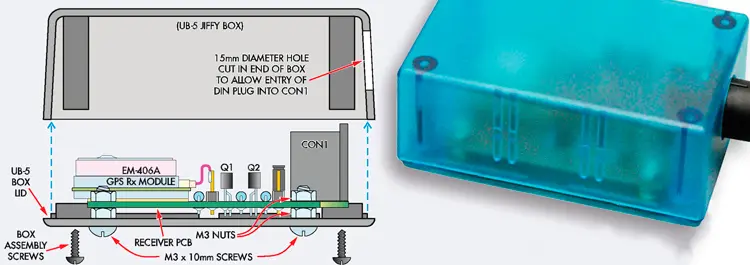
Fig. 6: here’s how to install the GPS 1pps Timebase Module in a UB-5 jiffy box. The module
(with CON1 installed) mounts on the case lid.
On the timebase board, the +5V lead connects to the +5V pad, the ground wire to the GND pad, and the signal lead to the ‘1PPS’ pad. These pads are also labelled ‘1’, ‘2’ and ‘3’ (corresponding to the pin numbers for CONl, which is left out if the timebase is mounted inside the counter case).
Table 1: Resistor Colour Codes
No. | Value | 4-Band Code (1%) | 5-Band Code (1%) |
1 | 22kΩ | red red orange brown | red red black red brown |
1 | 10kΩ | brown black orange brown | brown black black red brown |
2 | 2.2kΩ | red red red brown | red red black brown brown |
1 | 1kΩ | brown black red brown | brown black black brown brown |
1 | 100Ω | brown black brown brown | brown black black black brown |
Putting it to use
There are no setting-up adjustments to make before the GPS lpps Timebase is put to use, apart from setting jumper shunts LKl and LK2 to suit the GPS receiver module you’re using. Jumper shunt LKl is simply placed on the right if the module needs 5V, or on the left if it needs 3.3 V.
In most cases, jumper LK2 will need to be placed in the ‘upper’ position, although there may be some GPS modules which need it in the lower position. If you are in doubt about this and you have access to a scope, use it to check the polarity of the 1Hz output pulses. The 100ms-wide pulses should be positive-going, as shown in Fig.7. If they’re not, the remedy is to fit LK2 to the lower position.
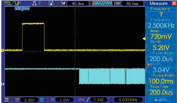
Fig. 7: the 1Hz pulses from the timebase must have positive-going leading edges, as
shown on the upper trace of this scope grab. In most cases, the GPS module will
provide pulses with this polarity, so link LK2 will have to go in the upper (noninverting)
position. If not, then set LK2 to the lower (inverting) position.
Alternatively, if you don’t have a scope you can easily determine the correct position for LK2 by trial and error.
Be aware that most GPS receiver modules will take some time to achieve a ‘fix’ from the GPS satellites after they are powered up. This startup period can be as long as 70-80 seconds, depending on the GPS module’s sensitivity, your location and the signal strength from the GPS satellites.
This means that until the module does achieve a fix, the 1Hz pulses from it will either be non-existent or ‘free running’ - ie, not locked to the GPS time reference. So don’t expect to be able to make high-accuracy measurements right from switch-on. You’ll need to wait a couple of minutes while the GPS receiver locks on to the GPS signals.
While you are waiting and assuming that you have selected the External Timebase option, the 12-digit counter will not usually show any measurement. Instead, it will continue to display ‘Silicon Chip’ until pulses are received from the timebase.
If you are impatient and don’t want to wait for the GPS lpps timebase to achieve a fix each time you switch the counter on, there’s a remedy for this too: keep it permanently powered from a separate 5 V DC plugpack. That way, the GPS-locked 1Hz timebase pulses will be available to the 12-Digit Frequency Counter whenever you want to use it.
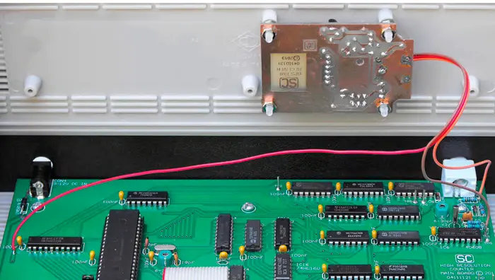
Fig. 8: This view shows the GPS 1pps Timebase Module mounted inside the 2.5GHz 12-Digit Frequency Counter. Note that the unit must be mounted on the lid so that it sits horizontally – important for the antenna to function effectively.
Author: Jim Rowe


