
 This handy Arduino Uno R3 compatible shield is intended for simple control applications in and around the house. When the system is connected to the Internet, the label "Internet of Things" (IoT) becomes applicable.
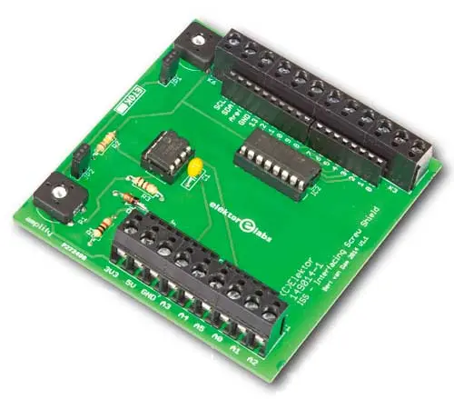
Wires to and from the shield [1] can be connected with a screwdriver - no soldering is required. The circuit on the board proper does not use all of the Arduino signals, and other shields can be stacked on it as long as they do not interfere with our board, making the system very flexible and extensible. The board is larger than your typical Arduino shield and its size allows the screw terminals and trimmers to remain accessible even when another shield is plugged onto it.
The board offers several expedient functions:
- a variable voltage source for biasing or powering sensors;
- an analogue input with adjustable gain for small signals;
- a current and voltage limited input for detecting a high voltage;
- six power transistor outputs for switching for instance lamps or relays.
Let's walk through the shield's functions step by step helped by Figure 1.

Figure 1. Just the facts, ma’am. A straightforward design without fancy tricks and hard-to-get components
Variable voltage source
Trimpot P2 provides a variable voltage between 0 and 5 V. If jumper JP1 is shorted this voltage is available on the Arduino's analog input A3. In this case it is also available at K1, pin 3, and can be used to control, bias or even power an external (low-current) device like a sensor. When JP1 is left open P2 has no function and this pin can be used as an analog input or a digital input/output.
Small signals
IC1A, powered from the 5-V line, is a rail-to-rail input-output operational amplifier (opamp) meaning that both its input as its output cover the range of 0 to 5 V (within a few millivolts). This output is connected to the Arduino analog input A0 only, hence its signal is not available on a screw terminal block. The opamp is wired as a non-inverting amplifier with its gain is controlled by P1. The maximum gain is about 100, the minimum gain, one. The result is that the input signal on K1, pin 1 can either be amplified or it can simply be buffered. Although the input impedance of the input is very high, it can be fixed at 100 kΩ by shorting JP2. Doing this is useful because it avoids the opamp struggling with noise, hum and other interference when its input is left open. If, on the other hand, the source connected to this input has a very high output impedance, it may be better to open JP2 to prevent squashing such a sensitive signal.
Detect high voltages
K1, pin 2 is a voltage and current limited analog input. Zener diode D1 will limit high DC voltages to 3.3 V maximum - a safe level for Arduino boards. But be careful, negative (AC) voltages are not allowed, not on this input and, by the way, not on any other input. R1 provides current limiting for both the input and D1. Its value is a little high, meaning that when you connect the input to, say, about 5 V, the voltage will be limited to around 3 V, but with an input voltage of 12 V or 15 V you will measure 3.3 V here. The purpose of this input is to detect voltages (much) higher than the Arduino can accept, for instance the output voltage of a DC adaptor or the state of a switch connected to a high voltage. Although in theory this input can easily withstand voltages up to 100 V, never ever connect it to the AC line voltage!
Powerful outputs
Part IC2, a ULN2003A, has a long-standing reputation, and a good one, which is why it was used here. In it are seven powerful Darlington transistors that can be controlled digitally. Although the device has seven channels, only six were used on this shield. Each transistor can switch 500 mA and can stand up to 50 V. These transistors are very good to switch something connected to a power supply (50 V max), a relay, a lamp or a motor for instance, to 0 V as they can handle relatively large currents. An Arduino output cannot do this without the help of such a driver circuit. In case you must switch more current than one channel can handle you can put two or more of these outputs in parallel. If you want to switch inductive loads (like a solenoid, relay or motor) you should add a flyback diode in parallel with the load (cathode to the power supply, anode to the output of IC2) as the chip's internal flyback diodes are not used on this board.
Some remarks
Power to the shield is supplied by the Arduino that carries it; do not power the shield through K7 when it is plugged onto an Arduino. This connector is intended for powering devices connected to the shield only, not to power the Arduino.
The 3.3-V output is the Arduino's 3.3 V output which is not very powerful, so treat it with loving care.
IC1 and IC2 are mounted in sockets so they can be replaced easily in case of a mishap.
Most of the Arduino extension signals have been brought out to sturdy screw terminals to allow easy connection of wires and cables to the board. Most, but not all: the serial port pins (pins 0 & 1), VIN, Reset, IOREF and AREF are only accessible on the shield connectors.

Web Links
[1] www.elektor.com/ interfacing-screw-shield-149014-91
[2] www.elektormagazine.com/160169
Author: Clemens Valens (Elektor Labs)