Presented here is a handheld device that can be used to measure magnetic field using a Hall effect-based sensor. The device can be used in the physics lab for conducting various experiments on magnetism. Moreover, some upgradations can be made to develop new and advanced devices. The device shows magnetic field in CGS (centimetre-gram-second system) unit, Guass and is updated every 250 milliseconds on the LCD screen.
Circuit and working
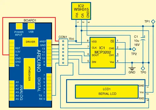
Fig.1 shows the circuit diagram of Ar-duino-based Gauss meter. The circuit is built around Arduino Uno board (Board1), MCP3202 12-bit analogue-to-digital (A/D) converter (IC1), WSH315 Hall-effect sensor (IC2) and serial LCD (LCD1).
Fig.1: Circuit diagram of Arduino-based Gauss meter
MCP3202 (12-bit A/D converter).
The Microchip Technology's MCP3202 is a successive approximation 12-bit A/D converter with an on-board sam-ple-and-hold circuit. It is programmed to provide a single pseudo-differential input pair or dual single-ended inputs. Differential non-linearity (DNL) is specified at ±1 LSB, and integral nonlinearity (INL) is offered in ±1 LSB (MCP3202-B) and ±2 LSB (MCP3202-C) versions. Communication with the device is done using a simple serial interface compatible with SPI protocol. The device is capable of conversion rates of up to 100ksps at 5V and 50ksps at 2.7V. The MCP3202 device operates over a broad voltage range of 2.7 V to 5.5V. Low-current design permits operation with typical standby and active currents of only 500nA and 375μA, respectively.
WSH315 (Hall-effect sensor).
This ratiometric, linear Hall-effect sensor accurately tracks extremely small changes in magnetic flux density, even those changes that are generally too small to operate Hall-effect switches. The device comes with a Hall-sensing element, linear amplifier and emitter-follower output stage integrated on a single IC to handle small analogue signals.
Arduino Uno board.
Arduino is an open source electronics prototyping platform based on flexible, easy-to-use hardware and software. It is intended for artists, designers, hobbyists and anyone else interested in creating interactive objects or environments. Arduino Uno is a board based on AT-mega328 microcontroller. It consists of 14 digital input/output pins, six analogue inputs, a USB connection for programming the on-board microcontroller, power jack, an ICSP header and a reset button. It is operated with a 16MHz crystal oscillator and contains everything needed to support the microcontroller. It is very easy to use as the user simply needs to connect it to a computer with a USB cable or power it with an AC-to-DC adaptor or battery to get started. The microcontroller on the board is programmed in Arduino programming language using Arduino development environment. Pins 10 through 13 of Board1 are connected to pins 1, 5, 6 and 7 of 12-bit ADC IC1, respectively. Pin 1 of Board1 is connected to RXD pin 3 of LCD1.
Test Points | |
Test point | Details |
TP0 | 0V, GND |
TP1 | 5V |
TP2 | Output of Hall-effect sensor |
PARTS LIST | |
Semiconductors : | |
IC1 | - MCP3202, 12-bit ADC |
IC2 | - WSH315, Hall-effect sensor |
LCD1 | - 16x2 serial LCD |
Capacitor: | |
C1 | - 10μF, 16V electrolytic |
Miscellaneous: | |
BOARD1 | - Arduino Uno board |
CON1 | - 7-pin connector |
The working of the project is simple. Hall-effect sensor IC2 has 3 pins: Vcc, Ground and Vout. The Vout of the sensor is connected to channel 0 (CH0) of ADC IC1 as shown in Fig. 1. IC1 is connected to Arduino controller in SPI mode. The sensor generates voltage output from 0.2V up to 4.8V for 5V power supply. Resolution of ADC IC1 is 5/212 = 1.22mV. The input voltage to channel 0 of the ADC IC1 gets converted to equivalent 12-bit binary data and is fetched by Ar-duino board in two bytes. Boardl then processes the digital data from IC1 and shows it on the serial LCD together with the Pole (North/South) indication.
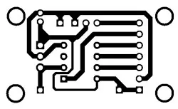
Fig. 2: An actual size, single-side PCB for the Gauss meter
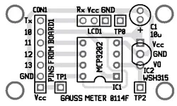
Fig. 3: Component layout for the PCB
EFY Note
The source code of this project is included in this month’s EFY DVD and is also available for free download on source.efymag.com website.
Software
The software is written in Arduino programming language and the board is programmed using Arduino IDE software. ATmega328 on Arduino Uno board comes preburnt with a bootloader that allows you to upload new code without the use of an external hardware programmer. It communicates using the original STK500 protocol. You can also bypass the bootloader and program the microcontroller through the in-circuit serial programming (ICSP) header, but using bootloader, it is quick and easy. Select Arduino Uno from the 'Tools > Board' menu (according to the microcontroller on your board) in the Arduino IDE and burn the program through standard USB port in the computer.
Construction and testing
An actual-size, single-side PCB for Arduino-based Guass meter is shown in Fig. 2 and its component layout in Fig. 3. Assemble the circuit on the provided PCB to minimise the assembly errors and save time. Use IC base for ADC IC1.
To test the circuit for proper functioning, check 5V power supply for IC1 and IC2 at TP1 with respect to TP0. The analogue voltage levels corresponding to magnetic field strength can be observed at TP2 using a multimeter.
Author: Ronie Adhiraaj Ghosh