When restoring vintage tube-type radios, it's essential to have a proper power input system. This system typically includes an isolation transformer, a Variac, and a current limiter. The Variac and current limiter protect the radio or other electronics from overvoltage and overcurrent, while the isolation transformer protects the technician from a potentially hazardous hot chassis that's connected directly to the power mains. In this article, we will review the proper configuration of the isolation transformer for vintage electronic gear.
Hardware
In Figure 1, we see three examples of line isolation transformers. From left to right, they are an unmodified one amp BK Precision unit, a modified 15 amp Xentek boat anchor, and a modified 2.1 amp Tripp-Lite unit. The BK Precision unit is ready to use as an isolation transformer because its input and output circuits are completely isolated, but both the Xentek and Tripp-Lite require minor modifications, which will be discussed later in the article.
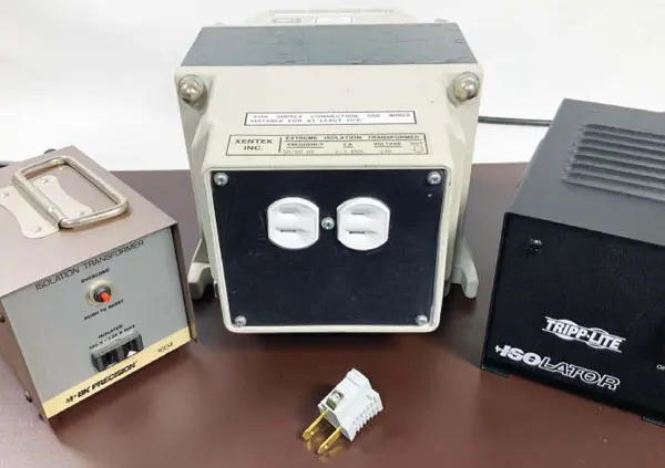
Figure 1. Line isolation transformers from my workbench
Science
A typical commercial line isolation transformer, as shown in Figure 2, consists of a 1:1 transformer with 120 VAC across hot and neutral. The input's ground lead is connected to the output's ground lead, and the neutral lead on the output winding, along with an electromagnetic Faraday shield, is tied to ground. This configuration minimizes noise transfer, but there's still a shock hazard if someone who is grounded touches the hot lead.
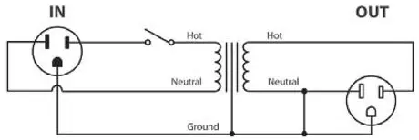
Figure 2. Schematic of a typical commercial line isolation transformer
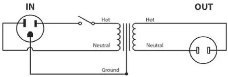
Figure 3. Schematic of a modified line isolation transformer. Note the input ground pin does not extend to the output
In Figure 3, we see a modified line isolation transformer that provides true isolation between input and output. Regardless of the primary circuit's configuration relative to ground, the secondary circuit is completely isolated from the primary and ground. This means that there's no shock hazard if you touch the hot or neutral line from the transformer secondary or the chassis of a radio connected directly to one of the secondary leads. The only hazard is coming between both hot and neutral on the secondary.
Mods
To modify a line isolation transformer, you need to remove the wire that connects the ground connection to the output connection and replace the three-prong grounded outlet with a two-prong ungrounded outlet, as shown in Figures 4-5. By removing the three-prong fixture, you remove the possibility of positioning yourself between ground and hot or neutral.
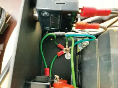
Figure 4. Original common ground connection on the Tripp-Lite
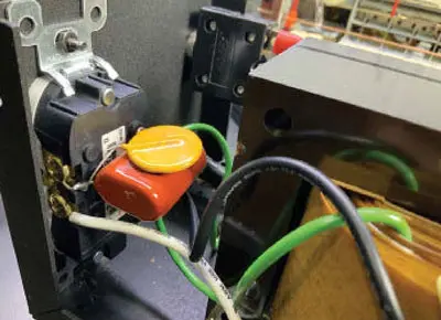
Figure 5. Replacing the Tripp-Lite's three-prong grounded outlet with a two-prong ungrounded outlet
In Figures 6-8, we see how to modify a boat anchor (Xentek) to serve as an isolation transformer. The modification required was to replace the three-prong 220 VAC outlet with a two-prong 125 VAC outlet. To add extra safety, a power switch and a slow blow 1 5A fuse were added to the primary circuit, as shown in Figures 6 and 7. The secondary side of the Xentek is shown in Figure 8, where the secondary is completely isolated from the ground wire, which was not used.
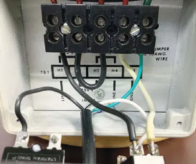
Figure 6. Adding a switch, fuse, and indicator light on the input end of the Xentek
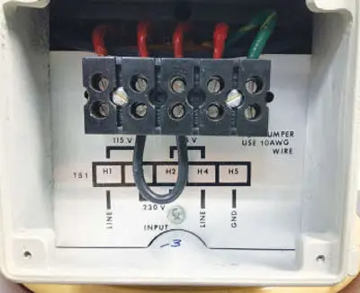
Figure 7. Completed primary side of the Xentek
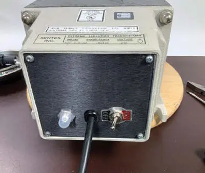
Figure 8. Secondary side of the Xentek showing separate ground connection
Proper Use
It's important to remember that this configuration of the isolation transformer is specific to working with vintage radio circuits that don't have a power transformer but instead connect directly to the power mains. Figure 9 shows the configuration of isolation transformers as part of the AC supply system that's used to test and run vintage radios and other vintage tube equipment. Figure 10 shows the Variac, bulb current limiter (front), and Xentek isolation transformer (rear).

Figure 9. Isolation transformer as the first element in the power delivery chain on my workbench
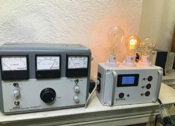
Figure 10. The Variac, bulb current limiter (front), and Xentek isolation transformer (rear)
In conclusion, line isolation transformers are crucial when restoring vintage tube-type radios. By properly configuring the isolation transformer, technicians can protect themselves and the vintage gear they're working on from overvoltage and overcurrent, and eliminate the shock hazard associated with directly connecting to the power mains.
This article explains the proper configuration of an isolation transformer in the context of restoring vintage tube-type radios. The isolation transformer serves to isolate the technician from a potentially hot (i.e., 125 VAC) radio chassis, which is connected directly to the power mains.
The hardware used for the isolation transformer can vary, but the article provides examples of three different units: a 1 amp BK Precision unit, a 15 amp modified Xentek boat anchor, and a modified 2.1 amp Tripp-Lite unit.
The science behind the isolation transformer involves creating a true isolation between the input and output, so that the secondary circuit is completely isolated from the primary and from ground. This eliminates the shock hazard for someone who is grounded and touches the hot lead. To achieve this, the ground lead of the input must not extend to the ground lead of the output.
The article explains how to modify a typical commercial line isolation transformer to achieve true isolation. The modification involves removing the ground connection from the output and replacing the standard three-prong AC outlet with a dual two-prong outlet that isn't grounded. The article provides step-by-step instructions and photos for modifying both a Tripp-Lite unit and a Xentek boat anchor.
The proper use of the isolation transformer involves using it as the first element in the power delivery chain, as shown in Figure 9. The article concludes by showing a photo of the isolation transformer in use, as part of the author's AC supply system for testing and running vintage tube equipment.
