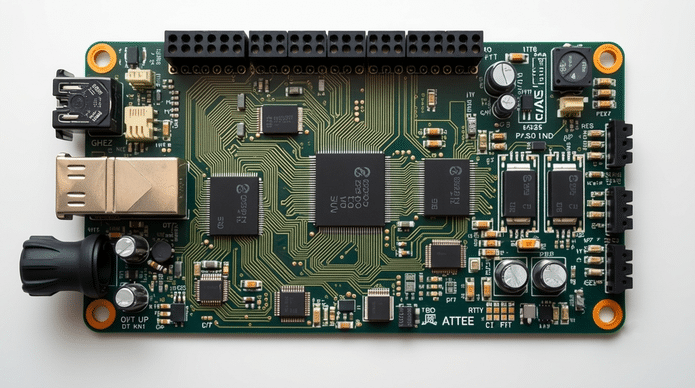
Open-hardware Electrical Testing Board for automated device testing
Researchers from Universidad Autónoma de Ciudad Juárez have developed an open-hardware Electrical Testing Board that provides in-circuit and functional testing capabilities at a fraction of the cost of industrial automated test equipment. The complete system can be built for approximately $790 and is intended for prototyping, education, laboratories, and small-scale manufacturing.
Open-hardware Electrical Testing Board for automated device testing
The system routes signals between programmable power supplies, measurement circuits, comparators, pull-up/pull-down networks and protection circuitry. It is not intended to replace high-end industrial ATE — it supports one device under test per board and does not include inductance measurement or JTAG boundary scan.
Design files, schematics, firmware and bill of materials are publicly available for replication and modification.
Source: Electronics For You