Datasheets

Datasheets search archive of electronic components

For search electronic components datasheets (documentation) use the search form or sortcuts for quick datasheet search. Our base has over 1 000 000 downloadable pdf datasheets. If you don't find necessary datasheet, please send feedback to project administrator. We hope, what our electronic components datasheets and documentation archive help you find necessary documentation.

MACP-010561-001SMB-

Name: MACP-010561-001SMB
Producer: M/A-COM
Download datasheet: Download
Description:
Detailed description:

MACP-010561

MACP-010561

Temperature Compensated Directional RMS Power Detector 2 - 6 GHz 

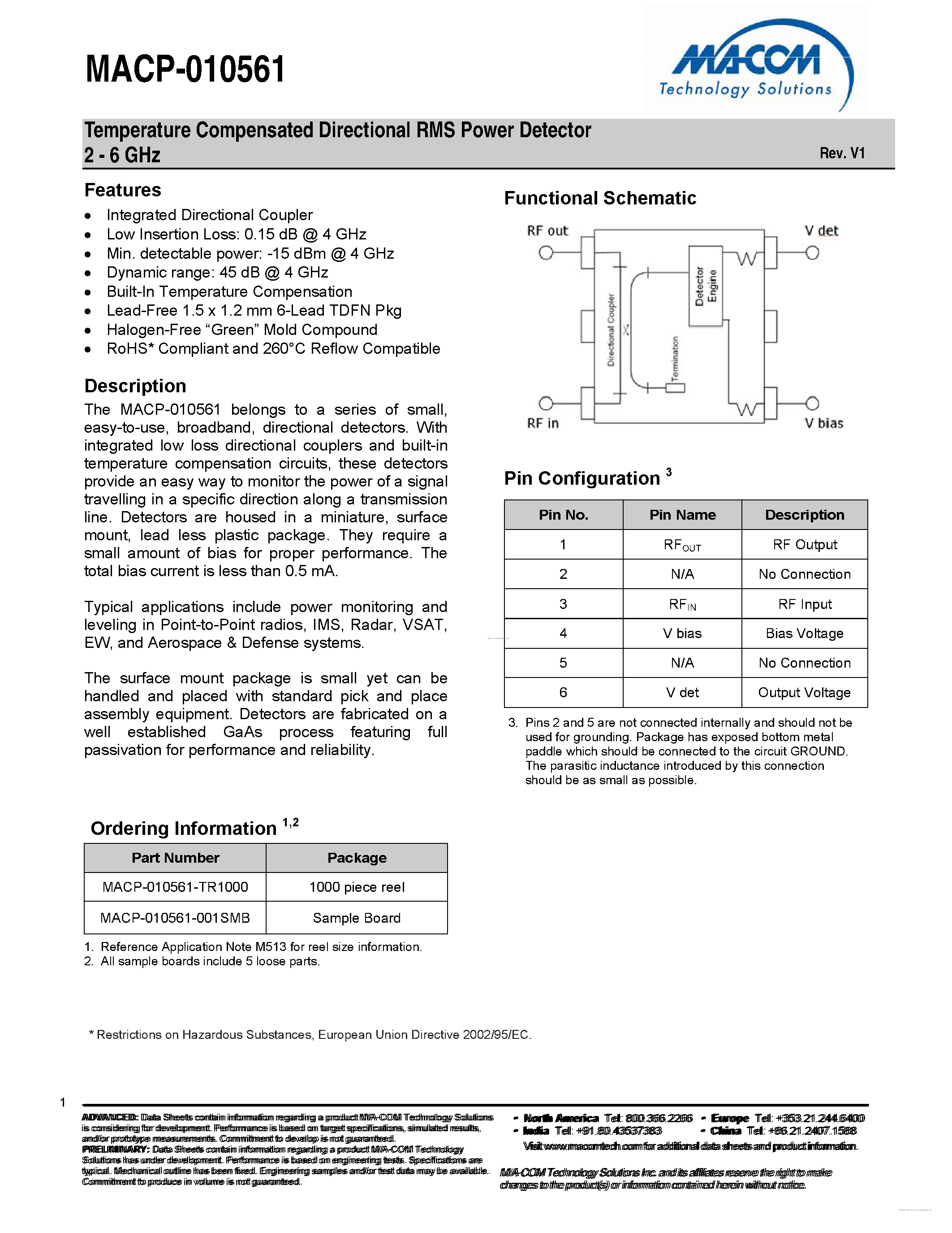
Features  Integrated Directional Coupler  Low Insertion Loss: 0.15 dB @ 4 GHz  Min. detectable power: -15 dBm @ 4 GHz  Dynamic range: 45 dB @ 4 GHz  Built-In Temperature Compensation  Lead-Free 1.5 x 1.2 mm 6-Lead TDFN Pkg  Halogen-Free “Green” Mold Compound  RoHS* Compliant and 260°C Reflow Compatible 

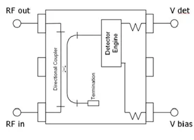
Description The MACP-010561 belongs to a series of small, easy-to-use, broadband, directional detectors. With integrated low loss directional couplers and built-in temperature compensation circuits, these detectors provide an easy way to monitor the power of a signal travelling in a specific direction along a transmission line. Detectors are housed in a miniature, surface mount, lead less plastic package. They require a small amount of bias for proper performance. The total bias current is less than 0.5 mA. Typical applications include power monitoring and leveling in Point-to-Point radios, IMS, Radar, VSAT, EW, and Aerospace & Defense systems. The surface mount package is small yet can be handled and placed with standard pick and place assembly equipment. Detectors are fabricated on a well established GaAs process featuring full passivation for performance and reliability. 

Functional Schematic

Pin No.

Pin Name

Description

1

RFOUT

RF Output

2

N/A

No Connection

3

RFIN

RF Input

4

V bias

Bias Voltage

5

N/A

No Connection

6

V det

Output Voltage


3. Pins 2 and 5 are not connected internally and should not be used for grounding. Package has exposed bottom metal paddle which should be connected to the circuit GROUND. The parasitic inductance introduced by this connection should be as small as possible.
Others with the same file: MACP-010561-001SMB | MACP-010561-TR1000
MACP-010561
Datasheet MACP-010561-001SMB - page 1
Datasheet MACP-010561-001SMB - page 2

More 1 000 000 datasheets example: LM317