Даташит поиск по электронным компонентам в формате pdf на русском языке. Бесплатная база содержит более 1 000 000 файлов доступных для скачивания. Воспользуйтесь приведенной ниже формой или ссылками для быстрого поиска (datasheet) по алфавиту.Если вы не нашли нужного Вам элемента, обратитесь к администрации проекта .
Более 1 000 000 datasheetsнапример: LM317
MACP-010561-001SMB-
Наименование:
MACP-010561-001SMB
Производитель:
M/A-COM
Скачать даташит (datasheet):
Описание:
Подробное описание:
MACP-010561
Temperature Compensated Directional RMS Power Detector 2 - 6 GHz
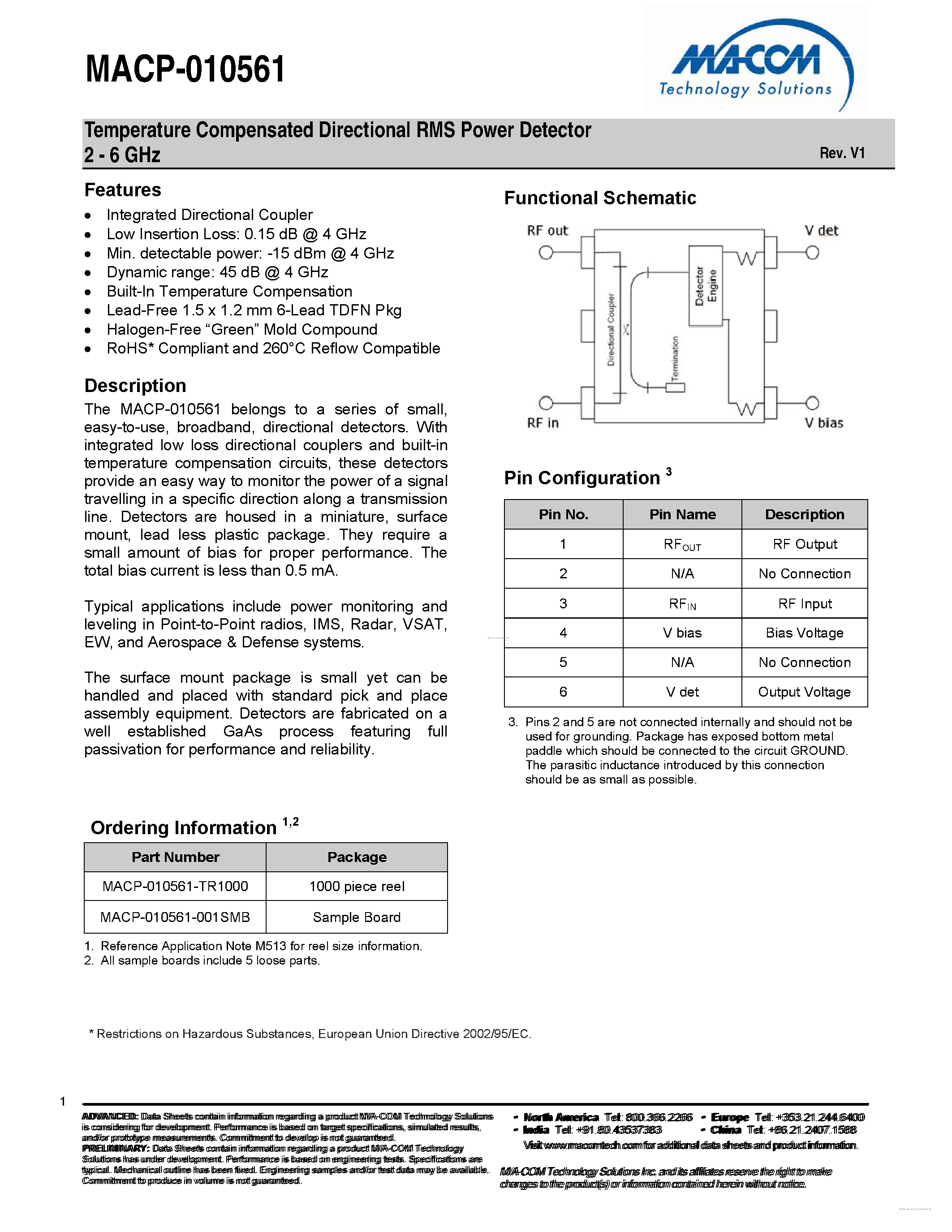
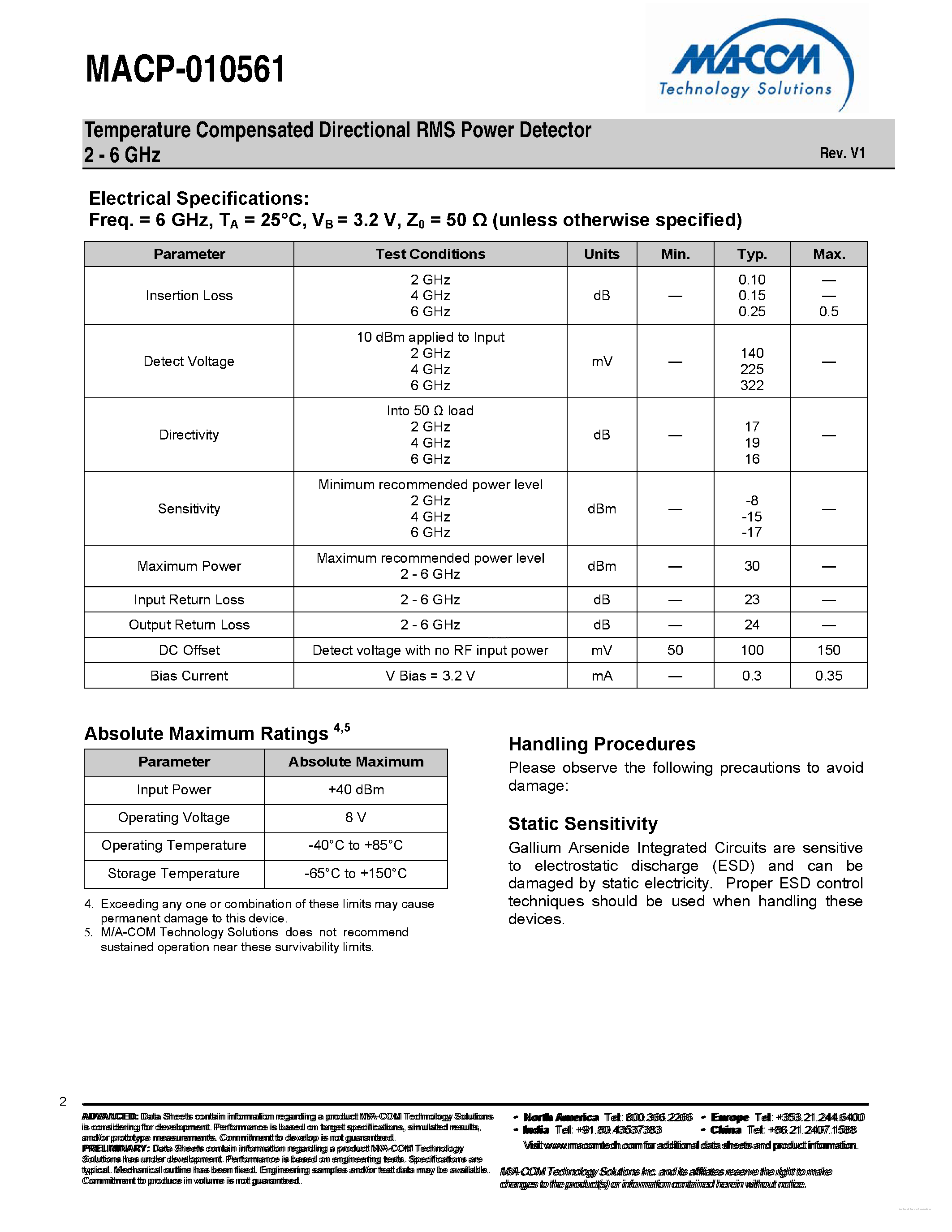
Features Integrated Directional Coupler Low Insertion Loss: 0.15 dB @ 4 GHz Min. detectable power: -15 dBm @ 4 GHz Dynamic range: 45 dB @ 4 GHz Built-In Temperature Compensation Lead-Free 1.5 x 1.2 mm 6-Lead TDFN Pkg Halogen-Free “Green” Mold Compound RoHS* Compliant and 260°C Reflow Compatible
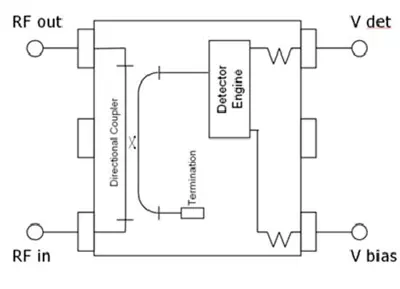
Description The MACP-010561 belongs to a series of small, easy-to-use, broadband, directional detectors. With integrated low loss directional couplers and built-in temperature compensation circuits, these detectors provide an easy way to monitor the power of a signal travelling in a specific direction along a transmission line. Detectors are housed in a miniature, surface mount, lead less plastic package. They require a small amount of bias for proper performance. The total bias current is less than 0.5 mA. Typical applications include power monitoring and leveling in Point-to-Point radios, IMS, Radar, VSAT, EW, and Aerospace & Defense systems. The surface mount package is small yet can be handled and placed with standard pick and place assembly equipment. Detectors are fabricated on a well established GaAs process featuring full passivation for performance and reliability.
Functional Schematic
Pin No.
Pin Name
Description
1
RFOUT
RF Output
2
N/A
No Connection
3
RFIN
RF Input
4
V bias
Bias Voltage
5
N/A
No Connection
6
V det
Output Voltage
3. Pins 2 and 5 are not connected internally and should not be used for grounding. Package has exposed bottom metal paddle which should be connected to the circuit GROUND. The parasitic inductance introduced by this connection should be as small as possible.