A faulty power supply is the most common reason why an LCD or LED TV will not turn on, shuts itself off, or keeps clicking at start-up. This guide describes a step-by-step troubleshooting procedure that works for most Samsung, LG, Philips, Sony, Vestel, TCL and other TV power boards. At the end you will find links to schematic diagrams of specific TV power supplies.
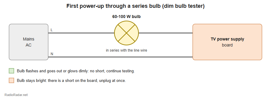
Fig. 1. Dim bulb tester: first power-up of a TV power supply through a series bulb
In most modern TVs the power supply is a separate board, often combined with the backlight driver (such boards are called IP boards). A typical structure:
The main board turns the supply on through the ON/OFF line (also marked PS_ON, STB_ON or POWER_ON). The backlight has its own enable signal, BL_ON (BACKLIGHT_ON), and brightness is set by the DIM (PWM_DIM) signal.
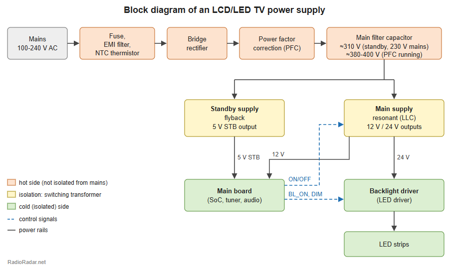
Fig. 2. Block diagram of an LCD/LED TV power supply
| Symptom | Likely cause | Check first |
|---|---|---|
| Dead set, standby LED off | standby supply, blown fuse, short on the primary side | fuse, DC voltage on the main capacitor, standby output |
| Fuse blown and blackened inside | hard short on the primary side | bridge rectifier, PFC MOSFET, main supply MOSFETs, X/Y capacitors |
| Standby LED on, but the TV does not turn on | main supply or PFC does not start, no ON command from the main board | ON/OFF signal, PFC voltage, 12/24 V outputs |
| Turns on and shuts off at once, LED blinks | protection trips: overload, backlight fault, output voltage drop | output capacitors, backlight LEDs, outputs under load |
| Clicking, restarts in a loop | dried-out electrolytic capacitors, unstable feedback | standby and main supply capacitors, optocoupler and TL431 in the feedback loop |
| Sound but no picture (dark screen) | backlight or backlight driver failure | LED strips (shine a flashlight on the screen: if you see a faint image, the backlight is off), driver output |
| Whistling or squealing | chokes and transformers, dry capacitors, no load on the outputs | capacitors, loose windings |
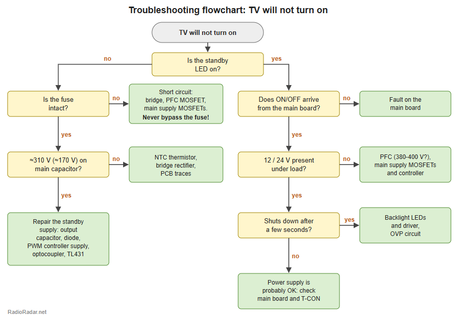
Fig. 3. TV will not turn on: power supply troubleshooting flowchart
Remove the board and inspect it under good light. Look for:
Capacitors that look fine but have lost capacitance or have high ESR are behind a large share of successful repairs. Check them with an ESR meter.
Never just replace a blown fuse: a blackened fuse means a short circuit. Test the bridge rectifier, the PFC MOSFET, the main supply MOSFETs and the standby switch (or the controller IC with a built-in switch). See our guide How to test a transistor with a multimeter. Never bypass the fuse with a piece of wire.
Power the board through the bulb and measure the DC voltage on the main capacitor. In standby it should be about 1.41 x mains voltage: around 310-325 V on 220-240 V mains or about 170 V on 120 V mains. If there is no voltage, check the thermistor, the bridge and the traces after the fuse.
Measure the standby voltage at the output connector (usually 5 V, marked STB, 5V_STB or 5VS on the board). If it is missing or clearly low, check:
If the standby voltage is fine without load but drops when the main board is connected, the problem is probably a short on the main board.
Turn the TV on with the remote and check whether the ON/OFF signal reaches the power board. The active level and voltage depend on the model, so check the schematic or the markings near the connector. If the signal never arrives, the fault is most likely on the main board, not in the power supply.
To test the power board on its own, you can tie the ON/OFF line to the standby output through a 1-10 kOhm resistor (if the signal is active high). Put a load on the outputs, for example a 12 V car bulb on the 12 V rail. Many boards will not start or will run unstable without a load.
After the ON command, the voltage on the main capacitor should rise to about 380-400 V. If it stays at 310 V and the board has a PFC stage, check the PFC MOSFET, the boost diode, the controller and its supply. On many boards the PFC and main supply controllers are powered only after the ON command, through a separate transistor switch or relay.
Measure the output voltages under load. If the supply starts and then goes into protection, check the output Schottky diodes, the capacitors and the overvoltage protection (OVP) circuit. A very common reason for a TV shutting down after a few seconds is a failed backlight LED: the driver detects an open or shorted strip and turns the TV off.
More TV schematics are in the TV circuit diagrams section. Datasheets for PWM controllers and power MOSFETs are in the datasheet search.