How to Test a Transistor and MOSFET with a Multimeter
You can test a transistor with an ordinary digital multimeter set to diode test mode (the diode symbol on the dial). In this mode the meter shows the voltage drop across a p-n junction in millivolts or volts, and "1" or OL on the display means that no current flows. This guide covers bipolar transistors (BJT) and MOSFETs, how to identify the pins, and what you can and cannot check with the transistor still on the board.
Before you start
- Unplug the device and discharge the capacitors, especially in power supplies.
- The most reliable test is on a transistor removed from the board. In circuit, other parts and transformer windings are connected in parallel with the junctions and can give misleading readings.
- Find the pinout in the datasheet. Transistors in the same package can have different pin orders. Use the RadioRadar datasheet search.
- In diode test mode the red probe is normally positive. This is true for most handheld meters, but check it on a known good diode.
How to test a bipolar transistor (BJT)
To a multimeter, a bipolar transistor looks like two diodes joined at the base. In an NPN transistor the anodes of these "diodes" are at the base, in a PNP transistor the cathodes are.
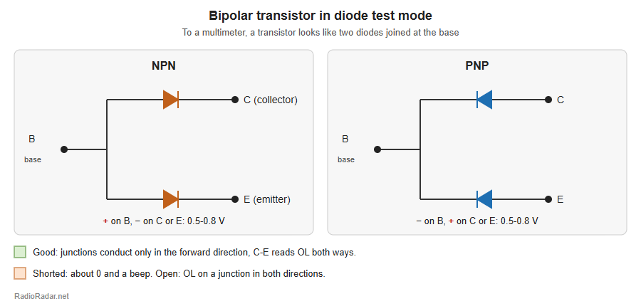
Fig. 1. NPN and PNP transistor in multimeter diode test mode
NPN transistor
| Red probe (+) | Black probe (-) | A good transistor reads |
|---|
| Base | Emitter | 0.5-0.8 V (silicon) |
| Base | Collector | 0.5-0.8 V, usually slightly lower than base-emitter |
| Emitter | Base | OL (open) |
| Collector | Base | OL |
| Collector | Emitter | OL |
| Emitter | Collector | OL |
PNP transistor
The same, but with reversed polarity: put the black probe on the base and the red probe on the emitter and then the collector. A good transistor reads 0.5-0.8 V in these two measurements and OL in all others.
Germanium transistors have a lower junction drop, about 0.15-0.35 V.
Signs of a bad transistor
- Shorted: about 0 V and a beep between any pair of pins, most often collector-emitter.
- Open: OL in both directions on a junction that should conduct.
- Leaky: a junction conducts in the reverse direction, or there is some reading between collector and emitter instead of OL.
How to identify BJT pins
- Find the pin that conducts to both other pins with the same probe on it. That is the base.
- If the red probe is on the base, the transistor is NPN. If the black probe is, it is PNP.
- Compare the two readings: the junction with the slightly higher drop is usually base-emitter. The difference is only a few to a few tens of millivolts, so confirm with the datasheet.
- If your meter has an hFE socket, insert the transistor according to its type. The correct pin order gives a noticeably higher gain reading.
Transistors that test differently
- Darlington transistors: the base-emitter drop is about 1-1.4 V, because two junctions are in series.
- Digital (pre-biased) transistors with built-in resistors: the meter shows a resistance between base and emitter, not a diode.
- Horizontal output transistors with a built-in damper diode: a diode conducts between collector and emitter in one direction, and there is a resistor of a few tens of ohms between base and emitter. This is normal.
How to test a MOSFET
A MOSFET has three pins: gate (G), drain (D) and source (S). The gate is insulated from the channel, so a good transistor always reads OL between the gate and the other pins. Most power MOSFETs have a built-in body diode between drain and source.
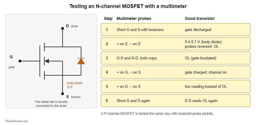
Fig. 2. How to test an N-channel MOSFET with a multimeter
N-channel MOSFET
- Discharge the gate: short G and S for a second with tweezers or a probe.
- Check the body diode: red probe on S, black on D. A good transistor reads about 0.4-0.7 V. Swap the probes: it should read OL.
- Check the gate insulation: G-S and G-D should read OL in both directions.
- Turn the transistor on: touch G with the red probe and S with the black probe. The meter charges the gate.
- Check the open channel: red probe on D, black on S. If the transistor has turned on, the meter shows a low reading instead of OL.
- Turn it off: short G and S. The D-S channel should read OL in this direction again.
If the MOSFET turns on and off and the gate is insulated, it is almost certainly good.
P-channel MOSFET
The procedure is the same with reversed polarity. The body diode conducts with the red probe on D and the black probe on S. To turn the transistor on, put the black probe on the gate and the red probe on the source.
If the multimeter cannot turn the MOSFET on
Most handheld meters supply only a few volts in diode test mode. That is enough for logic-level MOSFETs, but transistors with a 3-4 V gate threshold may not turn fully on. In that case charge the gate from a 9 V battery through a 1-10 kOhm resistor (plus to G, minus to S), then measure the D-S channel. Do not exceed the maximum gate-source voltage from the datasheet, usually +/-20 V.
Signs of a bad MOSFET
- About 0 V and a beep between D and S in both directions with the gate discharged: shorted channel. This is the most common failure in switch-mode power supplies.
- Any reading between G and S or G and D instead of OL: gate insulation breakdown.
- The transistor does not turn off after G and S are shorted.
A shorted switching MOSFET in a power supply often takes the source resistor, the gate driver or PWM controller and the fuse with it. Check them as well before powering the device after replacement.
How to identify MOSFET pins
- Power MOSFETs in TO-220 and TO-247 packages are most often pinned G-D-S (looking at the marking, pins down), with the metal tab connected to the drain. This is common but not universal, so check the datasheet.
- Without a datasheet, find the pair of pins with the body diode: these are D and S. The remaining pin that does not conduct to either of them is the gate. The direction of the diode tells you which is the drain and which is the source, and the channel type.
Can you test a transistor without removing it?
Partly. In circuit, a multimeter reliably shows a short: if collector-emitter or drain-source reads close to zero, remove the transistor and test it on its own. However, a transformer winding in parallel or a shorted neighbouring part can give the same reading, so an in-circuit "short" must always be confirmed out of circuit.
Related on RadioRadar