LiFePO4 BMS: How to Choose and Wire a Battery Management System
LiFePO4 (lithium iron phosphate) battery packs are now widely used for backup power: with inverters and UPS units for routers, lighting and pumps, in solar systems and in DIY power stations. A pack of several cells in series must never be used without a BMS (Battery Management System) board. This article explains what a BMS does, how to choose one for your pack and how to wire it correctly.
Why you need a BMS
Lithium cells cannot tolerate overcharge or deep discharge, and in a series string their voltages drift apart over time. A lead-acid battery partly balances itself, but an unmanaged lithium pack quickly ends up with one cell overcharged and another over-discharged. A BMS takes care of this:
- it stops charging when any cell exceeds the upper limit;
- it disconnects the load when any cell drops below the lower limit;
- it protects against overcurrent and short circuit;
- it balances the cell voltages;
- with temperature sensors, it blocks charging when the temperature is out of range.
Key LiFePO4 voltages
| Parameter | 1 cell | 4S (12 V) | 8S (24 V) | 16S (48 V) |
|---|
| Nominal voltage | 3.2 V | 12.8 V | 25.6 V | 51.2 V |
| Maximum charge voltage | 3.65 V | 14.6 V | 29.2 V | 58.4 V |
| Practical charge voltage | 3.45-3.55 V | 13.8-14.2 V | 27.6-28.4 V | 55.2-56.8 V |
| Discharge cut-off | 2.5 V | 10.0 V | 20.0 V | 40.0 V |
Exact limits are given in the datasheet for your cells, so follow it. Charging to 3.45-3.55 V per cell instead of the maximum costs only a small part of the capacity and extends cell life.
How to choose a BMS
1. Chemistry and cell count
BMS boards are made separately for Li-ion (NMC) and for LiFePO4, because the protection limits differ. For LiFePO4 the overcharge cut-off is about 3.65-3.75 V per cell and the over-discharge cut-off about 2.0-2.5 V. The number of series cells (4S, 8S, 16S and so on) must match your pack.
2. Current rating
Calculate the load current from power: I = P / (U x efficiency). For example, a 1000 W inverter on a 12.8 V pack with about 90% efficiency draws roughly 1000 / (12.8 x 0.9) = 87 A. For this load you need a BMS rated for at least 100-120 A continuous. Check the peak current rating separately if you run motor loads such as pumps or refrigerators.
3. Common port or separate port
- Common port: charger and load share one P- terminal. This is the most convenient option for inverters and UPS units with a built-in charger.
- Separate port: the charger has its own terminal (C-) and the load has P-. The charge current rating of such boards is often much lower than the discharge rating, so make sure it suits your charger.
4. Balancing
- Passive: excess energy on the highest cell is burned off in a resistor. Balance current is usually tens of milliamps. This is enough for packs of new matched cells but slow for cells with noticeably different capacity.
- Active: energy is moved from higher cells to lower ones, with currents from hundreds of milliamps to several amps. Useful for large packs and for used or unmatched cells.
5. Temperature protection
LiFePO4 cells must not be charged below 0 °C: this damages them. If the battery will sit in an unheated garage or shed, choose a BMS with a temperature sensor and low-temperature charge cut-off. In hot climates, high-temperature protection matters just as much.
6. Monitoring
Boards with Bluetooth or UART show cell voltages, current and temperature, and let you change the limits. This makes maintaining the pack much easier.
How to wire a BMS
Always study the wiring diagram in your board's manual first: the order can differ between manufacturers. A typical sequence:
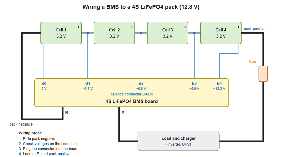
Fig. 1. BMS wiring diagram for a 4S LiFePO4 battery pack
- Build the pack and balance the cells. Before assembly, bring all cells to the same voltage. The best way is to connect them in parallel and charge them to 3.6 V from a bench power supply.
- Connect B-. The thick B- wire of the board goes to the pack negative, that is, the negative of the first cell.
- Check the balance connector before plugging it in. Solder the balance wires to the cells according to the diagram (B0/B-, B1, B2...). Without plugging the connector into the board, measure the voltage on each pin relative to the pack negative. For 4S they should rise in steps of about 3.2-3.4 V: roughly 3.3, 6.6, 9.9 and 13.2 V.
- Plug the balance connector into the board.
- Connect the outputs. The load and charger connect between P- (C-) of the board and the pack positive. The pack positive does not pass through the BMS, but it must have a DC fuse or DC circuit breaker rated for the current.
- Check operation. Many BMS boards must be activated after the first connection by briefly connecting a charger. Until then there is no voltage at the output.
Charging and inverter settings
- Charge with a LiFePO4 charger or a CC/CV power supply. For 4S the end-of-charge voltage is 14.2-14.6 V.
- Lead-acid chargers are not always suitable. Desulfation and equalization modes raise the voltage above 15 V, which is not acceptable for a lithium pack. If the charger has such modes, turn them off.
- Set the low-voltage cut-off of the inverter or UPS above the BMS limit, for example 11.5-12 V for 4S. Then the BMS protection trips only in an emergency.
- In a solar system, set the charge controller to a LiFePO4 profile or a user profile with the voltages from the table above.
Common mistakes
- Plugging in the balance connector with the wires in the wrong order is the most common way to destroy a BMS.
- A BMS rated exactly for the load current. Without headroom the board overheats and trips on inrush current.
- Thin wires and no fuse on the pack positive.
- Cells with different capacity and internal resistance in one pack. Passive balancing cannot compensate for that.
- Charging in freezing conditions without a temperature sensor.
Related on RadioRadar