
Electromechanical energy meters have been the standard for metering the electricity since billing began. But these are now being gradually replaced by electronic digital energy meters. Presented here is a simple energy meter using Analog Device's ADE7757 chip for single-phase, 2-wire (phase and neutral) systems used in households. IC ADE7757 is a low-cost, single-phase solution for electrical energy measurement. You can use this solution even for individual appliances to see how much energy they are consuming.
Its salient features are:
1. Can read up to 999999 units (kWh) with a resolution of 0.01 units
2. Designed for normal 230V AC and maximum line current of 30 amps
3. The meter count is 100 pulses/ kWh, i.e., 100 pulses will be required to register one unit
Circuit and working
Fig. 1 shows the circuit diagram of the energy meter which is built around energy-metering IC with integrated oscillator ADE7757 (IC1), microcontroller AT89C52 (IC2), EEPROM AT24C02 (IC3), 5V voltage regulator 7805 (IC5), opto-coupler MCT2E (IC4) and an LCD display.
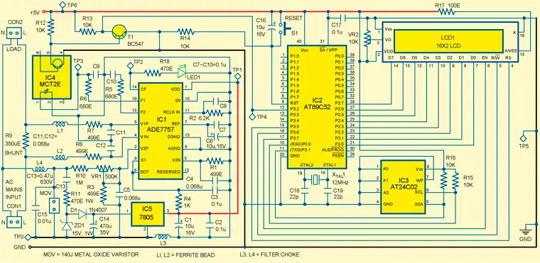
Fig. 1: Circuit diagram of the energy meter
IC ADE7757. It is a low-cost, singlechip solution for electrical energy measurement. In operation, the chip interfaces with a shunt resistor (used as the current sensor) and AC analogue voltage sensing the inputs and outputting the consumed power as explained below. It has two analogue input channels designated as V1 and V2, respectively. Channel V1 (also called 'current channel') is used for current sensing and channel V2 (also called 'voltage channel') is used for voltage sensing. The differential output from the current-sensing resistor is connected between V1P and V1N inputs, whilst the differential output signal proportional to the AC line voltage, obtained through a resistor divider, is connected between pins V2P and V2N.
TABLE I. Test Points
Test point | Details |
TP0 | 0V, AGND |
TP1 | 5V (w.r.t. TP0) |
TP2 | Train of pulses of frequency32 times of TP3 |
TP3 | 100 pulses/kWh |
TP4 | 100 pulses/kWh |
TP5 | 0V, GND |
TP6 | 5V (w.r.t. TP5) |
IC ADE7757 has a reference circuit and a fixed DSP function for calculation of the real power. A highly stable oscillator integrated into the chip provides the necessary clock for the chip. It supplies the average real-power information on the F1 and F2 low-frequency outputs. The meter is designed for 100 pulses/kWh and the pulses can be counted by any counter for power consumption calculation. Here, microcontroller AT89C52 is used for counting the pulses. ADE7757 provides a high-frequency output at the calibration frequency (CF) pin (here, it is 3200 pulses/kWh), which is selected via S1 and S0 pins as shown in bold in Table II. This high-frequency output provides instantaneous real-power information, which is used to speed up the calibration process. Functional block diagram of ADE7757 is shown in Fig. 2.
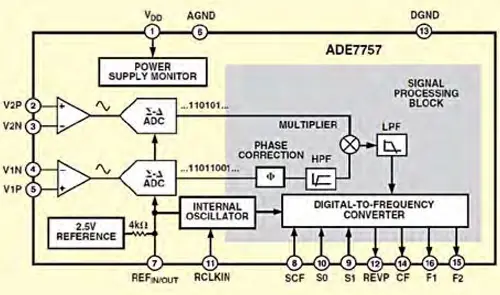
Fig. 2: Functional block diagram of ADE7757
TABLE II. Output Frequency on CF Pin
SCF | S1 | S0 | CF signals (Hz) |
1 | 0 | 0 | 128 X F1, F2 |
0 | 0 | 0 | 64 X F1, F2 |
1 | 0 | 1 | 64 X F1, F2 |
0 | 0 | 1 | 32 X F1, F2 |
1 | 1 | 0 | 32 X F1, F2 |
0 | 1 | 0 | 32 X F1, F2 |
1 | 1 | 1 | 16 X F1, F2 |
0 | 1 | 1 | 2048 X F1, F2 |
The power supply for IC ADE7757 is derived directly from mains using the capacitor divider network comprising C13 and C14. Most of the voltage is dropped across C13 (0.47μF polyester capacitor rated for 630V), whilst resistor R11 (470-ohm, 1W) is used as the current limiter. The output across C14 is limited to 15V DC, which serves as an input to regulator IC5. The regulated 5V is fed to IC1. The F1 output of IC1 is coupled to port pin P3.2 of microcontroller IC2 via opto-coupler IC4 whilst LED1 indicates that IC1 is working.
AT89C52. It is a low-power, high-performance CMOS 8-bit microcontroller that provides standard features: 8k bytes of Flash, 256 bytes of RAM, 32 I/O lines, three 16-bit timers/counters, a six-vector two-level interrupt architecture, a full-duplex serial port, on-chip oscillator and clock circuitry.
Microcontroller IC2 takes the meter reading through its pin 12 and stores it in EEPROM IC3, and at the same time displays it on the LCD, which requires additional 5V regulated and isolated supply (to avoid extension of live mains to the counter section). A conventional 5V regulator circuit incorporating a bridge rectifier (BR1), smoothing capacitor (C20) and regulator IC 7805 (IC6) has been used for the purpose. Fig. 3 shows the additional power supply.
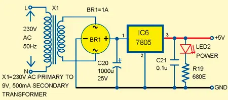
Fig. 3: Additional power supply for the counter circuit
Pins 21 through 28 of microcontroller IC2 are connected to the LCD data pins D0 through D7, respectively.
Pins 15, 16 and 17 of IC2 are connected with the control pins RS, R/W and EN of LCD, respectively. Power-on reset is provided by the combination of resistor R14 and capacitor C16. Switch S1 is used for manual reset. A 12MHz crystal along with two 22pF capacitors provide basic clock frequency to the microcontroller. Preset VR2 is connected with pin 3 of LCD for contrast control.
AT24C02. It is an I2C-bus compatible 2-kilobit EEPROM organised as 256x8 bits that can retain data for more than ten years. To obviate the loss of latest setting in the case of power failure, the microcontroller can store all data of user in the EEPROM. The memory ensures that the microcontroller will read the last saved data from EEPROM when power resumes. Using SCL and SDA lines of EEPROM, the microcontroller can read/write the data from/to AT24C02 memory. SCL and SDA lines of IC3 are interfaced to pin 10 and 11 of microcontroller IC2, respectively.
EFY Note
The source code of this project is included in this month’s EFY DVD and is also available for free download on source.efymag.com website.
Software
The source program for the microcontroller is written in C language and compiled using the 'Keil μVision4' compiler. The generated hex code is burnt into the microcontroller by using a suitable programmer. On reset/ power-on, the microcontroller executes the main function. The interrupt INT0 and LCD are initialised first. Message 'Energy Meter' and reading are displayed in first and second lines on LCD module. Continuous loop in the code reads the data from EEPROM and displays in the second line of LCD module. Header file i2c.h is used for I2C protocol communication and lcd.h is driver file for LCD.
Construction and testing
An actual-size, single-side PCB for the energy meter is shown in Fig. 4 and its component layout in Fig. 5. Assemble the circuit on the PCB to minimise assembly errors. IC1 is an SMD package so should be soldered on the solder side of the PCB. Use IC bases for other ICs.
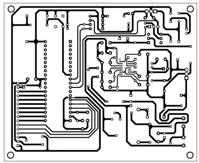
Fig. 4: An actual-size, single-side PCB for the energy meter
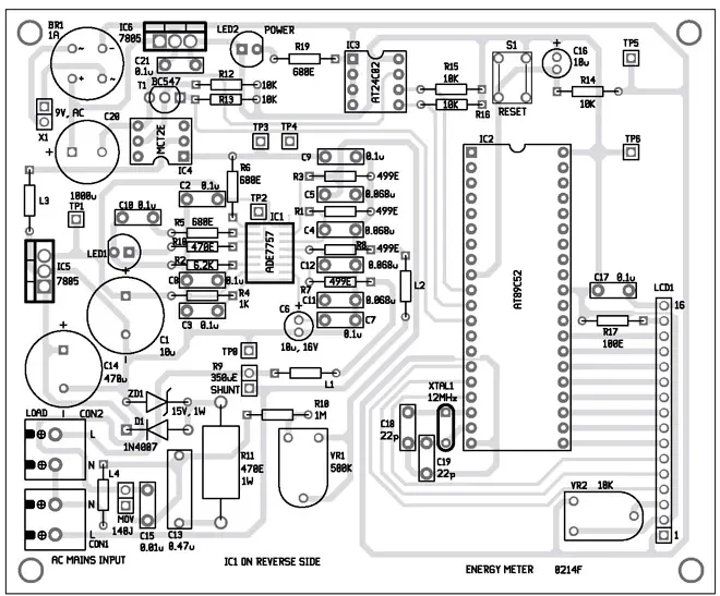
Fig. 5: Component layout for the PCB
Parts List
Semiconductors: | |
IC1 | - ADE7757 energy metering IC |
IC2 | - AT89C52 microcontroller |
IC3 | - AT24C02 EEPROM |
IC4 | - MCT2E opto-coupler |
IC5, IC6 | - 7805, 5V regulator |
T1 | - BC547 npn transistor |
D1 | - 1N4007 rectifier diode |
LED1, LED2 | - 5mm LED |
LCD1 | - 16x2 LCD |
BR1 | - Bridge rectifier module 1A |
ZD1 | - 15V, 1W zener diode |
Resistors (all 1/4-watt, ±5% carbon, unless stated otherwise): | |
R1, R3, R7, R8 | - 499-ohm |
R2 | - 6.2-kilo-ohm |
R4 | - 1-kilo-ohm |
R5, R6, R19 | - 680-ohm |
R9 | - 350-micro-ohm shunt |
R10 | - 1-mega-ohm |
R11 | - 470-ohm, 1W |
R12-R16 | - 10-kilo-ohm |
R17 | - 100-ohm |
R18 | - 470-ohm |
VR1 | - 500-kilo-ohm preset |
VR2 | - 10-kilo-ohm preset |
Capacitors: | |
C1, C6, C16 | - 10μF, 16 V electrolytic |
C2, C3, C7-C10, C17, C21 | - 0.1μF ceramic disk |
C4, C5, C11, C12 | - 0.068μF ceramic disk |
C13 | - 0.47μF, 630V polyester |
C14 | - 470μF, 35V electrolytic |
C15 | - 0.01μF ceramic disk |
C18, C19 | - 22pF ceramic disk |
C20 | - 1000μF, 25 V electrolytic |
Miscellaneous: | |
X1 | - 230V AC primary to 9V, 500mA secondary transformer |
Xtal1 | - 12MHz crystal oscillator |
MOV | - 140J metal oxide varistor (14mm, 275V) |
L1, L2 | - Ferrite bead |
L3, L4 | - 3.5mm x 9mm axial, filter choke (bead core) |
S1 | - Tactile switch |
CON1, CON2 | - 2-pin 5mm terminal connector |
CON3 | - 2-pin connector |
Author: Sunil Kumar