
Being an electronics/electrical field engineer is a challenging job, and for a person engaged in this job T&M tools are just like weapons to a warrior in the war field. in many cases in india, people rely on ‘jugad’tools for a lot of test and measurement activities, but those are neither safe, nor accurate. So presented here are all the must-have tools for an electronics field engineer to perform his jobs safely and accurately.
Field engineers can work in a variety of jobs. They are specialists employed at companies that offer services to clients, and usually work in the field, i.e., locations owned by the client and not by the company at which they are employed. The locations can range from various production facilities and plants to oil fields. In the field, they can act as service representatives, oversee operations, install equipment and maintain and repair the existing equipment or supervise all engineering operations.
A lot of times in India, we see field engineers with strange tools such as a bulb holder connected to two wires for testing the continuity. These tools may do the job but are not safe and accurate. So here we present some basic tools for field engineers and discuss why and how they are used.
Clamp meter
Flow of electrical charge (current) is used to power everything from appliances at home to huge machinery at various industries. In cases where electricity-powered equipment need to be repaired, serviced, maintained or installed, clamp meters can be indispensable tools. A clamp meter is a device that measures various properties of an electrical current. It is a preferable device in the field due to its numerous advantages, including safety, efficiency, versatility and convenience. When clamp meters are used, you do not need to cut any wires, lowering the chances of fatal shocks. Clamp meters can give accurate readings, allowing engineers to quickly diagnose and resolve most problems. Fig. 1 shows a clamp meter.
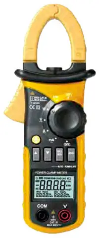
Fig. 1: A clamp meter
A clamp meter measures current, voltage, crest factor and continuity. AC current is the primary measurement that a clamp meter should be able to perform. These measurements are taken from different branches of a distributed system to debug the issue.
If an appliance is not working, the first thing to check is the input supply. Most clamp meters are capable of reading AC and DC voltages. These meters can also read crest factor which refers to the measurement of a waveform. The crest factor value is determined by the waveform's peak value versus its RMS value and is important in determining whether a circuit is overloaded. Continuity can also be checked using a clamp meter and the same is indicated with a beeprs. Table I shows various clamp meters available from different manufacturers.
TABLE I. Clamp Meters from Different Manufacturers
Specifications | Fluke Fluke 362 | Agilent U1211A | HIOKI 3288-20 | Metrix+ Mod: 4250T | IDEAL 61-775 | |
AC current | Range | 200A | 40A/400A/400-700A/700-1000A | 100/1000A | 1000A | 0.0-999.9A |
Resolution | 0.1A | 0.01A/0.1A/1A | 0.1A (100A range) | 1A | ||
Accuracy | 2% ±5 (45-65Hz) 2.5% ±5 (65-400Hz) | 1.0 % +5 (400-1000A) | 1.5% ±5 digits | 2% ±5 digits | 2% | |
DC current | Range | 200A | 40A/400A/1000A | 100/1000A | 1000A | 0.0-999.9A |
Resolution | 0.1A | 0.01A/0.1A/1A | 0.1A (100A range) | 1A | ||
Accuracy | 2% ±5 digits | 1.5% ±5 digits | 2% ±5 digits | 2% | ||
AC voltage | Range | 600V | 400V/1000V | 4.2/42/420/600V | 400mV-700V | 0.0-750.0V |
Resolution | 0.1V | 0.1V | 0.001V (4.2V range) | 1V | ||
Accuracy | 1.5% ±5 (45-400Hz) | 1 % ±5 digits | 2.3% ±8 digits | 1.5% ±5 digits | 1% | |
DC voltage | Range | 600V | 400V | 420m/4.2/42/420/600V | 400mV-1000V | 0.0-999.9V |
Resolution | 0.1V | 0.1 V | 0.1mV (420mV range) | 1V | ||
Accuracy | 1% ±5 digits | 0.5% ±5 digits | 1.3% ±4 digits | 1% ±3 digits | 1% | |
Resistance | Range | 300/3000Ω | 4000/ 4kΩ | 420-41.99MΩ | 400Ω-40MΩ | 0.0-999.9 0hm |
Resolution | 0.1/10 | 0.1Ω/0.001kΩ | 0.1Ω (420Ω range) | 10kΩ | ||
Accuracy | 1% ±5 digits | 0.5% ±3 digits | 2% ±4 digits | 1.5% ±5 digits | 2% | |
Continuity | ≤700 | Yes | Yes | Yes | Yes | |
Dimensions | 205x60x22mm | 106x273x43mm | 57x180x16mm | 249x89x38mm | 270x103x48.5mm | |
Clamp opening | 18mm | 52mm | 35mm diameter | 52mm | 51mm | |
Weight (gm) | 196 | 625 | 150 | 360 | 500 (including battery) | |
Safety reading | CAT III 600V | CAT III 1000V/CAT IV 600V | CAT III 600V (current) CAT III 300V (voltage) | IEC 61010-1 | CAT IV, CAT III |
Insulation resistance tester
Eighty per cent of electrical maintenance and testing involves evaluating insulation integrity. Harsh installation environments, especially those with extreme temperatures and/ or chemical contamination, cause deterioration to the insulations and, as a result, personnel safety and power reliability can suffer.
So it is important to identify this deterioration as quickly as possible so you can take the necessary corrective measures. Fig. 2 shows an insulation resistance meter.
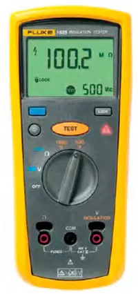
Fig. 2: Insulation resistance meter
To test the insulation, we apply a highly regulated, stabilised DC voltage across a dielectric and measure the amount of current flowing through that dielectric, and then calculate the insulation resistance using Ohm's law. The current here is the leakage current and the resistance is in mega ohms. This value of resistance is used to evaluate the integrity of the conductor.
Generally, positive and negative leads are put across an insulation barrier. A third lead, which connects to a guard terminal, may or may not be available with every tester. After the connections are made, test voltage is applied for a minute, which is a standard industry parameter that allows you to make relatively accurate comparisons of readings from past tests done by other technicians. During this interval, the resistance reading should drop or remain relatively steady.
Larger insulation systems will show a steady decrease, whereas smaller systems will remain steady because the capacitive and absorption currents drop to zero faster than on larger systems. After one minute, you should read and record the resistance value. Table II shows insulation resistance testers from different manufacturers.
TABLE II. Insulation Resistance Testers from Different Manufacturers
Specifications | Fluke Fluke 1507 | IDEAL Model: 61-797 | HIOKI IR4056-20 | Metrix+ DIT 3125 | |
Insulation secifications | Measurment range | 1507: 0.01MQ-10GΩ | Up to 20GΩ | Up to 4000MΩ | 0-1000GΩ |
Test voltage | 50V, 100V, 250V, 500V, 1000V | 50V, 100V, 250V, 500V, 1000V | 50V, 100V, 250V, 500V, 1000V | 30-600V | |
Test voltage accuracy | +20%, -0% | 0-20% | 2% ±5 digits | 2% ±3 digits | |
Short circuit current (mA) | 1mA nominal | 1mA nominal | 1.2mA or less | 1.3mA | |
Auto discharge | Discharge time <0.5 seconds for C = 1μF or less | Discharge time <1 second for C <1μF | Yes | Yes | |
Maximum capacitive load | Operable with up to 1μF load | Operable with up to 1μF load | Not specified | AC 1200V/10 sec | |
Measure accuracy | ±3% +5 (below 100V) | - | 4% | >100GΩ ±20% | |
Earth-bond resistance measurement | |||||
Range | 20Ω/200Ω/2000Ω/20kΩ | 10-1000Ω | |||
Resolution | 0.01Ω/0.1Ω/1.0Ω/0.01kΩ | 0.01 ohm to 40.00 kΩ | 0.01 Q (10Ω range) | ||
Accuracy | ±(1.5% +3) | 3% ±2 digits | |||
Overload protection | 2V RMS or DC | 600V AC RMS/DC | 600V AC | ||
Open circuit test voltage | >4.0V, <8V | >4.0V, <8V | 4.0V to 6.9V | ||
Short circuit current | >200.0mA | >200.0mA | 200mA or more | ||
Safety | Complies with ANSI/ISA 82.02.01 (61010-1) 2004, CAN/ CSA-C22.2 NO. 61010-1-04, and IEC/EN 61010-1 second edition for measurement category IV 600V (CAT IV) | Complies with UL/IEC/EN 61010-1, 61010-031, EN61557, EN 61326-1 +1A (EMC) Cat IV-600V | CAT III 600V | IEC 61010-1 | |
IP rating | IP40 | - | IEC 60529 (IP40) | ||
Dimensions | 203x100x50mm | 207x95x52mm | 159x177x53mm | 153x213x95 mm | |
Weight (gm) | 550 | 630 | 600 | 1030 |
Earth ground tester
A proper grounding system is of huge importance in the industrial and home environment. Proper grounding of metallic enclosures and support structures that are part of the electrical system helps avoid fatal shocks due to any kind of electrical system failure. The grounding system also provides protection against static electricity from tribocharging. Another important use of grounding system is protection against direct lightning strokes.
It is estimated that at least 15 per cent of the power quality problems are related to improper grounding. Therefore good grounding ensures that these problems do not escalate. Fig. 3 shows an earth ground tester and table III shows the testers from different manufacturers.
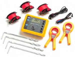
Fig. 3: Earth ground tester
TABLE III. Earth Ground Testers from Different Manufacturers
Specifications | Fluke Fluke 1621 | Metrix+ Model: DET 1503 | IDEAL 61-920 | |
General specifications | Measuring functions | Three-pole earth ground resistance, two-pole AC resistance of a conductor, interference voltage | 0.00-2000Ω | Ground resistance, ground leakage current |
Measuring rate | Two measurements/second | 5sec/V 2sec | 0/120/1200Ω | |
Safety | IEC/EN 61010-1, 600V CAT II, pollution degree 2 | IEC 61010-2031 | IEC61010-1: 2001 (CAT IV 300V Pollution degree 2), IEC61010-2-032: 2002 | |
IP rating | IP 40; IEC/EN 60529 | IEC60529 (Ip54) | IP 40 | |
Dimensions | 113x54x216mm including holster | 170x120x79mm | 246x119x53mm | |
Weight (gm) | 850 | 675 | 771 | |
Electrical specifications | Test voltage | 3.7kV | 0-200V | - |
Measuring time | 8 seconds (average from when start is pressed) | 10 sec-10 min | - | |
Electromagnetic compatibility | Emission: IEC/EN 61326 Class B, Immunity: IEC/EN 61326 Annex C | Yes | - | |
Interference voltage display | Vmax 30Veff Common mode rejection >80dB at 50Hz and 60Hz Ri 680kΩ Measuring uncertainty <10% for pure AC and DC signals | Yes | Yes | |
Measuring range resolution | Resolution 0.01Ω, display range 0-19.99Ω | 0.01Ω | ||
Resolution 0.1Ω, display range 20-199.9Ω | 0.1Ω | |||
Resolution 1Ω, display range 200-1999Ω | 1Ω | |||
RE resistance measurement | Open circuit voltage (Vac) | 23V to 24V AC | 220V | - |
Short circuit current (mA) | >50mA AC | 1.3mA | 0.1mA | |
Measuring frequency (Hz) | 128Hz | 50/60Hz | 2400Hz | |
Permissible overload (Veff) | 250Veff | 300V AC 30 seconds | - |
Laser distance meter
Laser distance meter can be a very useful tool for measuring distances with good precision without physical contact. In fact it allows for the most sensitive and precise length measurements, faster recordings encompassing large ranges. All these qualities do not come with a single technique so different techniques are used based on specific requirements. Some of the most important techniques used for laser distance meters are as follows:
1. Triangulation is a geometric method, useful for distances in the range of a millimetre to many kilometres.
2. Time-of-flight measurements (or pulse measurements) are based on measuring the time-of-flight of a laser pulse from the measurement device to some target and back again. Such methods are typically used for large distances.
3. The phase-shift method uses an intensity-modulated laser beam. Compared with other techniques, its accuracy is lower, but it allows unambiguous measurements over larger distances and is more suitable for targets with diffuse reflection.
4. Frequency modulation methods involve frequency-modulated laser beams, for example, with a repetitive linear frequency ramp. The distance to be measured can be translated into a frequency offset, which may be measured via a beat note of the sent-out and received beam.
Fig. 4 shows a distance meter.
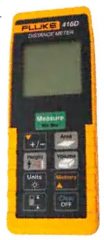
Fig. 4: Distance meter
Vibration tester
Machines are used in nearly every aspect of our daily life; from the vacuum cleaner and washing machine we use at home, to the industrial machinery used to manufacture nearly every product we use on a daily basis. When a machine fails or breaks down, the consequences can range from financial loss, personal injury and possible loss of life. For this reason, early detection, identification and correction of problems is paramount to anyone involved in the maintenance of industrial machinery to ensure continued, safe and productive operation.
Vibration levels give a very good idea of the state of a machine. It is evident from the fact that we naturally touch a rotating machine and feel the vibrations to see if it is running right. Even machines in the best of operating condition will have some vibration because of small, minor defects. Therefore each machine will have a level of vibration that may be regarded as normal or inherent. However, when vibration increases or becomes excessive, some mechanical trouble is usually the reason. Various instruments have been developed to actually measure a machine's vibration level and assign it a numerical value. Fig. 5 shows a vibration meter and Table IV shows features of some vibration meters from different manufacturers.
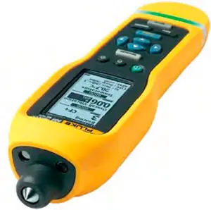
Fig. 5: Vibration meter
TABLE IV. Vibration Meters from Different Manufacturers
Specifications | Fluke Fluke 805 | MetrixTM Model: VB 8202a | MCM Instruments vibration tester AVD - 80 | Extech Instruments Extech 407860 | ||||
Range | Low frequency | 10Hz-1000Hz | 10Hz | 10Hz | 10Hz | |||
High frequency | 4000Hz-20,000Hz | 1000Hz | 1000Hz | 1000Hz | ||||
Vibration limit | 50g peak (100g peak-peak) | 0.1-4000Ω | 200mm/s | |||||
Sample rate | Low frequency | 20,000Hz | 10Hz | |||||
High frequency | 80,000Hz | 1000Hz | ||||||
Signal-to-noise ratio | 80dB | |||||||
Sensor | Sensitivity | 100mV g ±10% | Piezoelectric | |||||
Measurment range | 0.01g-50g | 0.1-400.0 m/s | ||||||
Resolution | 0.01g | 0.1mm/s | 0.5m/s2, 0.5mm/s, and 0.05mm | |||||
Safety | Accuracy | At 100Hz ±5% of measured value | 5% ±2 digits | ±(2% + 0.1mm/s) | ±5% ±2 digits | |||
IP rating |
| IP54 | ||||||
Dimensions | 241x71x58mm | 140x70x30mm | 180 x 72 x 32mm | |||||
Weight (gm) | 1160 | 150 | 200 | 395 | ||||
These are all the basic equipment that a field engineer would need depending on the project at hand. You can also add a multimeter to the list, which is also a useful tool in many cases. Refer buyers' guide on handheld digital multimeters published in Feb ruary 2013 issue for details.
Author: Ankit Gupta