



Electronics News
Archive : 24 September 2026 год
Researchers from Universidad Autónoma de Ciudad Juárez have developed an open-hardware Electrical Testing Board that provides in-circuit and functional testing capabilities at a fraction of the cost of industrial automated test equipment. The complete system can be built for approximately $790 and is intended for prototyping, education, laboratories, and small-scale manufacturing.
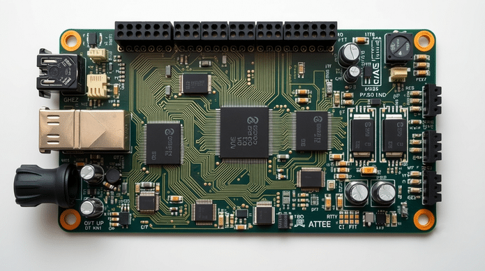
Open-hardware Electrical Testing Board for automated device testing
Key Characteristics
- Cost: ≈ $790 to build
- Board size: 187 × 160 mm, 4-layer FR-4
- Connector: 88-pin gold-finger for backplane integration
- Architecture: Three-board modular design
- Main PCB with functional test circuitry
- Relay PCB for signal switching
- Pluggable microcontroller board
- Main controller: Microchip PIC32MX795F512L @ 80 MHz
- Relay controllers: Two PIC18F4620 microcontrollers
- Test nodes: 16 nodes with relay-based switching buses
- Test cycle time: 10–50 ms per device
- Measurement ranges:
- Voltage: 0 – 100 V
- Current: 1 µA – 1 mA
- Resistance: 0.5 Ω – 1 MΩ
- Capacitance: 10 nF – 220 µF
- Measurement performance: Voltage and resistance errors typically below 1% (higher ranges)
- Bandwidth: DC to 10 kHz
- Communication: RS-232, opto-isolated UART, Ethernet
- Scalability: Up to 12 boards can be connected to one host for parallel testing
The system routes signals between programmable power supplies, measurement circuits, comparators, pull-up/pull-down networks and protection circuitry. It is not intended to replace high-end industrial ATE — it supports one device under test per board and does not include inductance measurement or JTAG boundary scan.
Open-Source Licensing
- Hardware: CERN Open Hardware Licence v2.0
- Firmware: GNU GPL v3.0
- Documentation: Creative Commons Attribution 4.0
Design files, schematics, firmware and bill of materials are publicly available for replication and modification.
Source: Electronics For You